+44 (0) 1793 784389
 +1 (855) 4-VIALITE
 sales@vialite.com
1:1 Redundancy
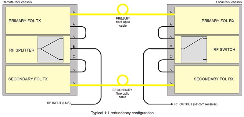
ViaLite fiber optic links can be configured into dual redundancy (1:1) systems to ensure maximum up-time. 1:1 redundancy is achieved by configuring the system using two transmitter modules with one RF splitter/combiner module at the transmit location, combined with two receiver modules and a redundancy switch module at the receive location.
Using the ViaLiteHD 1:1 redundant system in conjunction with the highly reliable RF cards gives five nines reliability (99.999%); often required for critical satellite communications and TT&C (Telemetry, Tracking and Command).
- 1:1 redundancy for L-Band HTS, GPS and wideband systems
- Maximizes link up-time
- Can be used to backup copper coax
- Manual and automatic control via SNMP
- Flexible configuration options
- 5-year warranty as standard
Product Inquiry


Low Loss
The ViaLite RF splitter/combiner module is a passive, low-loss, broadband, 1:2 power divider/combiner. The ViaLite redundancy switch module contains a broadband RF switch which provides very low insertion loss and very high levels of isolation.
Control
The RF switch is controlled automatically by sensing alarms on adjacent ViaLiteHD RF modules. Alternatively, it can be controlled directly by the user’s monitoring and control (M&C) equipment.
The primary and secondary RF receiver modules, and the redundancy switch module can be fitted into any position in a ViaLite 19” rack chassis. Dual cards and transceiver cards can also be used in redundant mode. Together with ViaLite dual redundant power supplies, this solution provides the highest possible up-time availability for the ViaLite system.
Read our guide to setting up a redundant link system.
75 ohm redundant systems are also available. Please contact us for more information using the product inquiry button above.
The ViaLiteHD switch and splitter are available in a couple of formats:
– Single rack chassis card / Dual rack chassis card (Rx/Rx, Tx/Tx or Tx/Rx)
A fully populated 19” 3U ViaLiteHD rack chassis supports up to 26 links and accepts 13 RF cards, plus a Monitoring & Control Module and dual power supply modules. A 1U chassis accepts three RF cards or two RF cards with a Monitoring & Control Module.
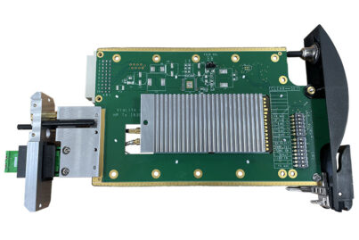
– Yellow OEM Link
The Yellow OEM Link has been designed for system integrators and equipment manufacturers to build the link into their own designs.
Splitter RF Performance Characteristics
| L-Band (50Ω) | L-Band + DC (50Ω) | Wideband (50Ω) | Wideband +DC (50Ω) | |
|---|---|---|---|---|
| Module | HRD-1-L1-0R-01 | HRD-2-L1-0R-41 | HRD-1-S1-0R-01 | HRD-2-S1-0R-41 |
| Frequency Range | 700-2450 MHz | 700-2450 MHz | 10-3000MHz | 10-3000MHz |
| Impedance | 50Ω | 50Ω | 50Ω | 50Ω |
| VSWR (typ)* | 1.5:1 | 1.5:1 | 1.5:1 | 1.5:1 |
| Insertion loss path S1 (typ) | 4.2 dB | 4.8 dB | 10-1000MHz – 3.9 dB 1000-2500MHz – 4.4 dB 2500-3000MHz – 5.3 dB | 10-1000MHz – 4.8 dB 1000-2500MHz – 5.5 dB 2500-3000MHz – 6.0 dB |
| Insertion loss path S2 (typ) | 4.2 dB | 4.8 dB | 10-1000MHz – 3.9 dB 1000-2500MHz – 4.3 dB 2500-3000MHz – 5.2 dB | 10-1000MHz – 4.8 dB 1000-2500MHz – 5.5 dB 2500-3000MHz – 5.5 dB |
| Isolation (typ) | 20 dB | 20 dB | 10-1000MHz – 20 dB 1000-2500MHz – 20 dB 2500-3000MHz – 18 dB | 10-1000MHz – 20 dB 1000-2500MHz – 20 dB 2500-3000MHz – 18 dB |
| Flatness full band (typ) | ±0.4 dB | ±0.4 dB | ±0.9 dB | ±0.9 dB |
| Max input signal | +24 dBm | +24 dBm | +24 dBm | +24 dBm |
| DC pass-through max current | No DC path | 0.8A (fused) | No DC path | 0.8A (fused) |
Splitter Temperature Characteristics
| All products listed above | |
|---|---|
| Operating temperature | -10 °C to +50 °C e |
| Storage temperature | -40 °C to +70 °C |
e Datasheet parameters based on temperature range -10 °C to +50 °C, refer to user manual for performance parameters at -20 °C to +60 °C.
Splitter Popular Configuration Example
HRD-2-S1-0R-01
RF splitter module with a wideband 10 MHz-3 GHz frequency range and 50 ohm SMA RF connector
3-Port Switch RF Performance Characteristics
| L-Band (50Ω) | L-Band + DC (50Ω) | Wideband (50Ω) | Wideband +DC (50Ω) | |
|---|---|---|---|---|
| Module | HRS-1-L1-0R-01 | HRS-4-L1-0R-41 | HRS-1-S1-0R-01 | HRS-4-S1-0R-41 |
| Frequency Range | 700-2450 MHz | 700-2450 MHz | 10-3000 MHz | 10-3000 MHz |
| Impedance | 50Ω | 50Ω | 50Ω | 50Ω |
| VSWR (typ)* | 1.5:1 | 1.5:1 | 1.5:1 | 1.5:1 |
| Max input signal | +24 dBm | +24 dBm | +24 dBm | +24 dBm |
| Insertion loss (typ) | 1.8dB | 2.3 dB | 10-50 MHz – 2.0dB.50-1000 MHz – 1.7 dB 1000-3000 MHz – 2.5 dB | 10-50 MHz – 3.0dB 50-1000 MHz – 2.5dB 1000-3000 MHz – 3.0dB |
| Isolation (typ) | 60dB | 60dB | 10-50 MHz – 70dB 50-1000 MHz – 70dB 1000-3000 MHz – 60dB | 10-50 MHz – 70dB 50-1000 MHz – 70dB 1000-3000 MHz – 60dB |
| Flatness full band (typ) | ±0.3dB | ±0.4dB | ±0.5dB | ±0.5dB |
| DC pass-through max voltage | - | 40 V | - | 40 V |
| DC pass-through max current | - | 0.8A (fused) | - | 0.8A (fused) |
3-Port Switch Temperature Characteristics
| All products listed above | |
|---|---|
| Operating temperature | -20 °C to +60 °C e |
| Storage temperature | -40 °C to +70 °C |
e Datasheet parameters based on temperature range -10 °C to +50 °C, refer to user manual for performance parameters at -20 °C to +60 °C.
Switch Popular Configuration
HRS-1-S1-0R-01
RF switch high isolation module with a wideband 10 MHz-3 GHz frequency range and 50 ohm SMA RF connector
ViaLiteHD RF Switch Datasheet (version HRS-x-DS-5)
ViaLiteHD RF Splitter Datasheet (version HRD-x-DS-3)
Yellow OEM Datasheet (version HRx-xx-xN-DS-6)
RF Support Module User Manual (version HRS-HB-13)