Automatic Gain Control
Automatic Gain Control (AGC) mode is a feature available in both ViaLite Transmitter and Receiver modules (including Dual Transmitter modules, Transceiver modules, etc.).
Download this Guide in PDF format
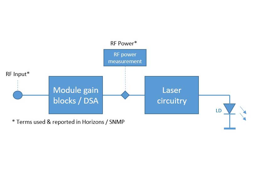
In order to set the AGC control on the module, and specifically for the transmitter module, it’s important to understand how RF signal power is measured and reported. The module RF power measurement circuit actually sits between the module gain / DSA block and the circuitry used to modulate the transmit laser. This is a RMS power measurement circuit and typically has a ~40 dB dynamic range. It is reported by Horizons / SNMP as “RF Power”. See diagram below.
RF Power Circuit Click here to expand
The 40dB dynamic range “window” can vary depending on which module type has been purchased, but for ViaLite’s most common transmit module, with a default gain setting of -11dB, the “RF Power” will typically measure and report between -25 dBm to +15 dBm.
There is also a term called “RF Input” reported by Horizons / SNMP. “RF Input” is a theoretical value derived from the RF Power and the settings applied to the gain blocks / DSA. “RF Input” should only be considered an estimate and in fact is not used in the actual process of setting up the AGC target value. But it is useful in describing that there will be an offset between the RF Power reported and the real input signal power entering the module.
So as an example, if we used the common ViaLite transmit module (Tx gain = -11 dB) an input signal power of -20 dBm (real power, not power reported by “RF Input”), could typically translate after the offset as -9 dBm reported as the “RF Power” value.
When AGC is enabled, the ViaLite module makes automatic adjustments to the module’s RF gain, in order to maintain an overall stable output level. This allows the ViaLite optical link to automatically compensate for small variations in the RF signal, as well as unwanted variations in fiber performance.
The AGC utilizes a closed loop control system, and adjusts the module’s internal RF gain by using one of the following sources as a reference:
- RF Input (ViaLite Transmitter modules only)
- RF Output (ViaLite Receiver modules only)
- Received Light Level (RLL) (ViaLite Receiver modules only).
In RLL mode, the Receiver attempts to compensate for the variations in optical loss over the fiber link, based on the nominal optical output power of a standard ViaLite Transmitter module. In this mode, the receiver is expecting to see an optical input of 4.5 dBm and will adjust the Receiver module gain to compensate for any optical loss. This option is only suitable if paired with a 3 mW laser Transmitter module.
If AGC is being used on one end of the link only, it is recommended to set AGC in the ViaLite Transmitter module.
If AGC is being used on both ends of a fiber link, the ViaLite Transmitter module should be set to RF Level mode, and the ViaLite Receiver module may be set to either RF Level mode or RLL mode.
In order to maximize the range of AGC to compensate for variations in the RF input to the link, then you should use RF power AGC for both the Transmitter and Receiver. Selecting RLL mode in the Receiver will only compensate for optical losses, not RF variations.
With all ViaLite links, it is always good practice to observe proper handling procedures for optical connectors. This is especially important with AGC as it may prevent issues such as dirty optical connectors or damaged cables from being detected.
Once AGC is enabled, the module automatically applies gain or attenuation to try to achieve the correct RF power level. If there is not enough gain or attenuation available in the module’s range, an alarm is raised. For SNMP monitoring, this alarm is output over the module’s control interface and will be detected by ViaLite HRC-3/Embedded Site Controller modules.
In this situation, the module will apply the maximum gain/attenuation available until the signal comes back into the gain range, when the module returns to compensate with AGC as normal, and the alarm will dismiss itself. This range is typically around 15.5 dB – the same as the available gain range in the other gain modes. If the AGC alarm activates, check all RF and optical connectors for cleanliness and serviceability before adjusting the AGC controls.
If SNMP monitoring is not available, or in use, please refer to the section on setting AGC using MGC later in this guide.
Setting and Controlling AGC Mode Using the HRC-3/Embedded Site Controller
ViaLite RF over fiber modules that are used in a chassis/enclosure fitted with an HRC-3 or Embedded Site Controller can set AGC mode remotely via SNMP or web GUI.
This setup allows you to receive alarm warnings when the signal varies outside of the AGC compensation range (these are recorded in the event log, and optionally output as SNMP TRAPs).
Steps
Step 1 – Select the module which you wish to apply AGC to: Transmitter (Tx), Receiver (Rx) or both.
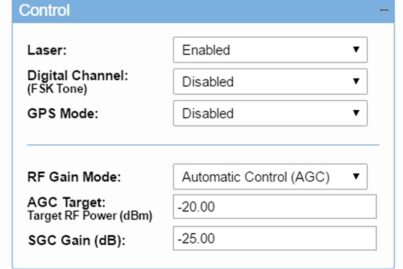
Step 2 – In the module control menu, select Software Gain Control (SGC) using the drop down box. This will allow you to set the system gain up without AGC to the level you require on your output
Set SGC gain levels (Tx) Click here to expand
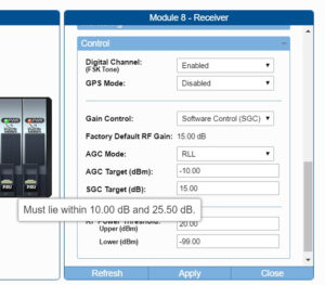
Hover over field to see limits – set SGC (Rx) Click here to expand
Step 3 – Using the SGC field, set the Tx gain and Rx gain in your system to achieve the performance and link gain required for your typical input. Hover over the field to see the available gain range for this module.
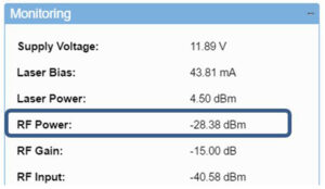
Step 4 – Once your system is operating with the gains required in SGC mode, note the RF Power value in the monitoring section of the web GUI.
RF Power – Tx Click here to expand
RF Power – Rx Click here to expand
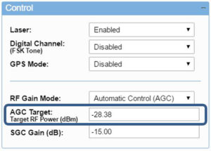
Tx Card control menu Click here to expand
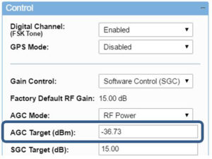
Rx Card control menu Click here to expand
Step 5 – Enter the RF Power value from step 4 into the AGC Target field.
Step 6 – Select the mode of AGC required (RF Power/RLL mode). The AGC target operates in steps of 0.5 dB, but will accept any decimal.
Remember to use the “apply” and “refresh” buttons on the SNMP menu each time you enter a value to check that the value has been accepted.
The system is now in AGC mode and will attempt to maintain a constant RF power output.
Setting and Controlling AGC Mode Using the Manual Gain Control (MGC)
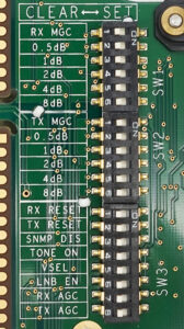
It is possible to use MGC to setup system gains ahead of activating AGC mode. Some modules are fitted with manual DIP switches that can be used to set the gain control mode. This is useful in deployments where an HRC-3 is not available (the recommendation, wherever possible, is to use SGC to setup system gains).
If the MGC DIP switches are to be used, please refer to the ViaLite RF Module handbook for guidance on setting MGC gain. The factory set values will typically be in the mid-range of the allowable gain setting range, to allow the operator to both increase and decrease the gain of the unit if desired.
Tx Card DIP Switch Click here to expand
Rx Card DIP Switch Click here to expand
TRx Card DIP Switch Click here to expand
Steps
- Unplug the module you wish to apply MGC (Tx, Rx or both).
- Using the cards DIP switches, select Tx and/or Rx MGC on.
- Set the gains up on your cards to provide the required outputs for your typical input.
- Once you have set your link to operate at the gain levels required, remove the card and select Tx and/or Rx AGC DIP switch to on, and select the MGC DIP switch to off.
The system is now operating in AGC mode and will attempt to maintain a constant RF power output. The mode of AGC operation in the Rx module will be determined at manufacture. This can only be altered using SNMP.
For Further information on AGC mode, or any other features of your ViaLite modules please contact ViaLite Customer Support.

 +44 (0) 1793 784389
 +1 (855) 4-VIALITE
 sales@vialite.com
